Boundary Layer (Tesla) Turbine Page
The Tesla Boundary Layer Turbine
Well...it sure does spin fast...real fast!
![[finished model]](./thumb/tt/assemble_08-t.jpg)
(Click on thumbnails to view fullsize images.)
NOTE: My most recent pages are back over at
www.stanford.edu/~hydrobay again.
![[Rainforest Site]](./gifs/rainforest.gif)
Click here for my polyphase motor/generator page.
Click here for my single-phase motor/generator page.
Click here for my solar powered fluid mechanics lab page.
Click here for my 3-axis CNC machine page.
Click here for my $662.00 supercomputer page.
![[best use any browser]](./gifs/vbrowser.gif)
![[under construction]](./gifs/constr.gif)
Home
Contents:
What it is?...
Well...an article about a Tesla blower from the September 1955 issue of Popular Science
provided below will help give you a notion of that. And, from the date, also indicate this isn't
exactly new technology. Basically it's flat discs with vent holes near their centers stacked up
on a shaft with thin spacers between. These discs are spun by directing some fluid (air, water,
burning gas, what-have-you) between them so that adhesion of the boundary layer of the fluid on
the surface of the discs drags them around as the fluid travels in from the outer edge of the discs
and out through the central vent holes. As the Popular Science article implies, it also
makes a good pump by spinning the shaft with a motor, where-by some fluid is sucked in through the
central vent holes and expelled out through the gaps between the rotating discs. This concept was
patented by Croatian immigrant inventor Nikola Tesla in around the year 1909.
Now, sorry to disappoint you zero-point energy, perpetual motion machine,
alternative energy source suppression conspiracy theorist, true-believer type folks.
I, sincerely, know your hearts really are in the right place. But, this ain't the Holy Grail.
Not even close. Ol' Tesla was a right clever guy, but also quite the showman [...those pictures
of him at Wardenclyffe sitting reading a newspaper outside the Faraday cage of his giant active
Tesla coil...double photographic exposure is the real hidden secret there...]. As well, sorry
to disappoint you Second Law of Thermodynamics touting, CRC Handbook of Chemistry
and Physics thumping true-disbeliever type folks, too. But, the minor flaws in
your understanding of how these things actually work somewhat outstripe your understanding of
the physics involved.
The Tesla boundary layer turbine is just that. A turbine. And, you use the same equations
to solve for its power output that you do for any other kind of turbine. The tricky bit is
calculating the energy transfer from the fluid stream to the rotating discs via the boundary
layer. (More on that to come).
In operation, a Tesla turbine is simply a turbomachine which is reasonably efficient at a
fairly high rotational speed, (dependant on several factors, including gap between the discs
and disc diameter), but not too efficient to get moving. The particularly good thing about
Tesla turbines is they are very easy to build. The better the quality of construction with
regard to alignment, balance, materials, and such, the better will be your turbine. But, it's
almost impossible to make one that won't work to some degree if you actually want it to.
Tesla blower article from Popular Science September 1955 issue:
The publication date happens to be the month and year of my birth.
...amazing what you can find on e-bay...
![[Pop. Sci. pg. 1]](./thumb/tt/ps55_tb_1-t.jpg)
![[Pop. Sci. pg. 2]](./thumb/tt/ps55_tb_2-t.jpg)
![[Pop. Sci. pg. 3]](./thumb/tt/ps55_tb_3-t.jpg)
What's up?...
Over time I will be documenting here my investigation of various means of constructing compressed
air driven boundary layer turbines, and their efficiencies. The first turbines will be constructed
using mainly bailing wire and spit techniques, from polystyrene sheet plastic, lexan, machine
screws, and glue. As the project progresses, and I settle in on a reasonable design, I'll make a
switch to aluminum disc runners. I'll also be looking at how to make compact three-phase
motor/generators for something to spin with the turbines. (See the links at the top of this page.)
I have a number of ideas on ways to computer model the energy transfer from the boundary layer
to the discs, (and access to some large computers). Eventually, those results will show
up here, too.
First test rotor (5.25" diameter, 10 discs):
(c.a., February 2001)
![[first test rotor]](./thumb/tt/greyrotorshaft-t.jpg)
![[first test rotor]](./thumb/tt/greyrotorspacing-t.jpg)
Constructed from 0.03" and 0.10" polystyrene sheet, and 0.125" and 0.375" polystyrene
tubing, it's easy to spin with just breath by gripping the bearings, and blowing into
the gaps between the discs at an angle a bit more than tangent to the circumference of
the discs. Blowing straight in towards the center shaft doesn't work well at all.
There seems to be a "sweet spot" angle for air flow somewhere between tangent and
perpendicular, closer to tangent than to perpendicular.
First test shrouded turbine (6" rotor diameter, 10 discs):
(c.a., April 2001)
![[first test shrouded turbine]](./thumb/tt/whiterotorside-t.jpg)
![[first test shrouded turbine]](./thumb/tt/whiterotoredge-t.jpg)
The disc and spacer stack assembly, (i.e., the "runner"), and the volute, (i.e., curved
housing which directs fluid from the nozzle to the runner, or vice versa), constructed
for this turbine were scaled from figure 1 in Nikola Tesla's 1918 US patent #1,061,142.
This patent is actually for a turbopump, but it was the only picture I had at the time.
It seems to work backwards just fine.
The turbine housing pieces were cut from standard 0.236" thick lexan sheet material using
a hand held electric jigsaw with a fine tooth wood cutting blade. To avoid excessive
vibration and cracking of the lexan material it was clamped between two pieces of 1/4"
plywood while cutting. Paper cutout patterns were taped to the plywood and followed with
the jigsaw. The lexan pieces were assembled by drilling and tapping them for, then screwing
them together with 2-56 flat head machine screws. All screw heads were set flush in the
lexan sheet by countersinking their entry holes. A sheet of thin, stiff, clear plastic was
glued in place to enclose the volute space, using acid free silicon sealer.
A close look at the two pictures above will show how the air inlet was assembled from two
pieces of 0.08" thick polystyrene sheet plastic and a piece of 0.375" OD polystyrene tube.
And, also how the thin clear plastic used to enclose the volute was set into thin cuts in
one of the 0.08" pieces of polystyrene sheet material in the inlet assembly. The air inlet
is attached by two 2-56 machine screws, one each in a hole tapped into the end of the two
lexan pieces cut to form the volute curve. The curved lexan pieces are attached to the
outer turbine lexan frame pieces via 2-56 screws which pass through countersunk holes in
the curved pieces and screw into tapped holes in the outer frame pieces.
The turbine discs and spacers, (the spacers are usually referred to as "star washers"), were
cut from 0.04" polystyrene sheet with tinsnips, then machined to uniform size and shape using
a small drill press with a jig that allows it be used as a vertical shape cutter. The runner
discs and star washers were glued in an alternating stack on a piece of 3/8" OD polystyrene
tubing. Once the stack was assembled, the central vent holes were further defined following a
paper pattern with a Dremel(tm) tool using a high speed hole saw for a bit.
Four discs were cut from 0.08" thick polystyrene, and pairs were glued together without spacers
to provide approximately 3/16" thick discs for the two outer runner discs. These thicker outer
discs help provide rigidity to the runner assembly.
Prior to assembling the runner, tweleve 0.125" holes were drilled to align around the circumference
of each disc. After assembling the runner, 0.125" polystyrene tubes were inserted into these holes
and glued in place. These tubes take the place of rivets in the original Tesla design.
The plumbing parts sticking out of one of the bearing mounts allow adjusting thrust on the bearings.
Thinwall brass tubing was slipped over the polystyrene shaft tube to back up the bearings and space
them from the runner. The brass tubing was cut to length to center the runner in the volute space.
The model spun right up with air from a shop compressor. The runner was statically balanced,
but the unit vibrated a lot. This, it seems, was mainly just a "flimsyness" issue with the
bearing mounts.
Reworked 6", 10-disc turbine:
Improved bearing mounts and larger bearings:
(c.a., June 2001)
![[reworked shrouded turbine]](./thumb/tt/bearingmounttics-t.jpg)
![[reworked shrouded turbine]](./thumb/tt/bearingmounthubangle-t.jpg)
![[reworked shrouded turbine]](./thumb/tt/bearingmounthub-t.jpg)
Besides beefing up the bearing mounts and installing larger diameter bearings, the polystyrene
tube shaft was reinforced by driving a 1/4" steel rod though its center hole. This rod fits
tightly enough so that it does not require gluing or pinning to the polystyrene tube to transfer
out mechanical power from from the spinning runner without slipping. One end of the steel rod
was threaded, and a 3/16" thick 1-5/8" diameter steel disc with a center hole and four surrounding
holes was threaded onto the shaft and then brazed in place to use for a mechanical mount point.
(Before driving it into the polystyrene center tube, of course.)
The thin plastic sheet used to enclose the volute space is held in place by double-sided foam
tape in the reworked version of the turbine, rather than the clear silicon sealer used in the
first version. For extra reinforcement, pieces of 0.125" polystyrene tubing were attached between
the turbine housing side plates so that they clamp the thin plastic sheet in place. This is just
a feels good feature. There really is no pressure buildup in the volute. You could even punch
drain holes in the bottom of the volute if moisture condenstation were a problem with no effect
on the turbine's operation.
Added 1.063 kg flywheel:
(c.a., December 2001)
![[reworked shrouded turbine]](./thumb/tt/flywheelside-t.jpg)
![[reworked shrouded turbine]](./thumb/tt/flywheelstraight-t.jpg)
![[reworked shrouded turbine]](./thumb/tt/flywheelangle-t.jpg)
![[reworked shrouded turbine]](./thumb/tt/flywheelclose-t.jpg)
The flywheel is approximately 5.34" in diameter cut from 3/8" steel plate. A coupling nut was
turned round over about three-fourths of its length, and a center hole was drilled in the
flywheel so that the turned portion of the coupling nut fits closely in the hole. Four more
holes were drilled around the flywheel's center hole to match with the holes with the mounting
plate on the 1/4" rod inserted in the turbine's polystyrene tube shaft. The flywheel is mounted
on the turbine by slipping its center hole over the threaded portion of the 1/4" rod that
extends from the mounting disc, then threading the turned end of the coupling nut onto the
threaded shaft while aliging the flywheel so the coupling nut passes through it's center hole.
When the coupling nut is threaded up snuggly against the mounting disc it provides support for,
and centers the flywheel on the 1/4" rod shaft. Then four 1/4"-20 screws are inserted through
the remaining holes in the flywheel and aligned with and threaded into the 1/4"-20 screw holes
in the mounting plate.
Now the turbine spins smoothly at over 2000 rpm, (measured with a model airplane prop tach),
when connected to a compressed air supply at about 75 psi, though a 25 foot long, 3/8" diameter
line. Though it really is very smooth, I'm nervous about trying to spin it much faster, given
the construction!
[...well, I actually did push it for all it was worth once...but didn't get close enough to try
and measure its rpm...concern about being around the flywheel rather than the rotor...it's going
damn fast before high frequency vibrations start it skittering about on the floor...]
It takes full flow from the shop air supply to get the turbine up to speed in a reasonable length of
time (though it will get up to speed eventually at much lower air flows). Once at speed, it takes
comparatively little flow to keep it at speed, even when adding a friction load to the flywheel
(toe of work boot on flywheel face).
One of these days I'll get another first stage regulator for my SCUBA tank, a variable area flow
meter, and few other odds and ends and use them to set up a flow metering bench. That, a tachometer,
and an alternator hanging off the turbine shaft with a variable load should be enough to do some
basic flow vs. power experiments.
A preliminary simulation:
(c.a., June 2002)
The code:
NOTE: If you picked up this program prior to 10 October 2005, there was a factor of 2 error in
the output. Although I described it in the comments, I neglected to account for runner discs
having two sides in the actual code. That has been fixed here now.
This program, TurbTorque.c, based on an article from TEBA News [1]
, is an application of straight forward fluid mechanics techniques, and not
a sophisticated model of real Tesla turbine operation. None-the-less, it does provide some
insight into the effects relative to rpm of two parameters on turbine operation, namely disc
diameter, and disc spacing.
The code simply computes values using prederived equations. The equations are obtained by noting
that only the tangential velocity component of the flow contributes to the shear stress on the
surface of a turbine disc, and that the force acting on a small area on the surface of a turbine
disc is equal to the shear stress at that area times the area. Torque on the small area is the
force on the area times the distance of that area from the center of the disc. And, power is
torque times angular velocity.
By double integration over the surface of the disc for the stress as given by the equation for
shear stress from steady flow between two parallel plates, and using the tangential velocity
obtained by differentiating the flow given in polar coordinates for a spiral vortex with a
central sink in two dimensional plane potential flow, a formula for the total torque on the
surface of the disc can be obtained which has only the disc spacing, and inner and outer radii
of the disc (vent radius and disc radius, respectively) as variables. The equation solves for
the total torque on one face of the disc, from which the power can be derived. Two times this
value gives the power contribution from one disc, and the product of that value with the total
number of discs minus 1 give the total turbine power. One is subtracted from the disc count to
remove the outer faces of the outside discs, which are assumed to make a negligible contribution
to the total power generated.
(Yes, I'll eventually flesh this out with equations. For now, refer to the TEBA News article.)
A better solution to the problem would be modeling of the real physics and solving the
Navier-Stokes equations for the system. In general solving the Navier-Stokes equations is not
easy to do, except for special cases, and exceptionally difficult for vorticies. Large computers
and new techniques for solving three dimensional physical systems will help.
The code presented below was written using the StormC 3.0 Professional C compiler for the Amiga
computer. There is a lot of Amiga specific code related to CLI input and output and the graphics
display you can probably ignore. If you are familiar with the Amiga you will notice some unfamiliar
library calls. I've been programming for a long time and have developed a number of my own
libraries for simplifying rote graphics and I/O coding. The equation solving section is below the
MAIN CODE separator comment.
![[TurbTorque.c]](./thumb/tt/turbtorque_c-t.jpg)
The results:
The results given below are from running the program for the following cases:
6 inch discs, 0.031 inch gap
6 inch discs, 0.020 inch gap
8 inch discs, 0.031 inch gap
8 inch discs, 0.020 inch gap
12 inch discs, 0.031 inch gap
12 inch discs, 0.020 inch gap
The progam takes user input for disc diameter and gap width. It assumes the same vent
diameter to disc diameter ratio as for Tesla's 9.75 inch turbine, and performs calculations
for 6, 9, 12, and 15 disc runner stacks with air as the working fluid over a range of 2000
rpm to 10000 rpm. The data are presented in both graphical and numerical form.
As can be seen from the data, faster is better, bigger is better, and closer is better...
(one of these days I'll do some percent difference calculations on the numbers...)
![[6 in. diam, .031 in. gap]](./thumb/tt/turb-6_031-t.jpg)
![[6 in. diam, .02 in. gap]](./thumb/tt/turb-6_020-t.jpg)
![[8 in. diam, .031 in. gap]](./thumb/tt/turb-8_031-t.jpg)
![[8 in. diam, .02 in. gap]](./thumb/tt/turb-8_020-t.jpg)
![[12 in. diam, .031 in. gap]](./thumb/tt/turb-12_031-t.jpg)
![[12 in. diam, .020 in. gap]](./thumb/tt/turb-12_020-t.jpg)
![[numeric output]](./thumb/tt/turbtorque_data-t.jpg)
A Spreadsheet Version:
(c.a., September 2005)
A spreadsheet version of the calculations from the turbtorque.c code,
turbtorque.xls, provides a bit more flexibility
in user input than does the original C program. If your web browsing system is set up with
a spreadsheet program that supports the .xls (Excel) format, (I use OpenOffice.org Calc
myself), then clicking the in-line link in the previous sentence should open the
turbtorque.xls spreadsheet for your use. If the spreadsheet doesn't open on your system, then
you should be able to save the file and try it on a system that does have a spreadsheet
program available.
The screen capture image below will be useful in following the short description of how to use
the spreadsheet program that follows:
![[turbtorque.xls]](./thumb/tt/SpreadCapture-1-t.jpg)
All parameters of the spreadsheet are free for editing. The simplest use is to change the
runner gap width and disc diameter values in the yellow block at the upper left corner of
the spreadsheet. Enter your desired data, (in inches), and the spreadsheet will calculate
and plot the potential power output (in horsepower-electric) for runners with the given
input gap and diameter having 6, 12, 9, 15, and 18 discs (including the wide outer discs)
over a rotational speed range of 0 to 27000 rpm. The legend to the right of the plot gives
the colors for the plot lines relative to the number of discs in each runner.
Besides varying gap and diameter values, you can also change the number of runner discs and
the rpm range. Below the plot are two green data blocks. Changing the "Mindiscs" and
"DiskStp" values in the upper block recalculates the "Ndiscs" row values, which give the
number of discs for each runner being simulated. The Mindiscs parameter gives the lowest
number of discs for a simulated runner, and DiskStp gives the number of discs to increment
up from the Mindiscs value for each runner in a simulation set. Similarly, changing the
"Minrevs" and "Revstp" parameters in the lower green block will recalculate the rpm
values in the "Rev" column, which give the rotational speed values for each simulation.
It is also possible to change the number of runner disc sets and the number of rpm values
for a simulation. The red data cells which are associated with the green cell blocks
allow this. Changing the "Numrun" value in the upper red block will change the number
of runner disc sets calculated from the Mindiscs and DiskStp values. Changing the "Numrev"
value in the lower red block will change the number of rpm values calculated from
the Minrevs and Revstp parameters. However, for changes in the Numrun and Numrev
parameters to have any visible effect, the correct number of cells in the Ndiscs row
and the Rev column must be added or deleted as required. The format of the cell formulas
can be found in the existing cells. You must increment the subtracted value in the last
cell by one in each added cell. Also, for the changes to be seen in the plot, the plot
range must be modified to include any added data values.
Major modification:
(c.a., April 2003)
![[housing assembly]](./thumb/tt/assemble_09-t.jpg)
![[housing assembly]](./thumb/tt/runnerout_01-t.jpg)
The reason:
Broke it...
An unfortunate bicycle incident, (the physics of which would be hard to describe unless you
happen to be familiar with the arrangment of my apartment), resulted in severe damage to the
main runner housing and a bent rotor shaft. The bent shaft was easy to straighten, but the
runner housing required extensive repairs. Rather than simply rebuild what was, I decided
to just keep the original 6" turbine runner, bearing mounts, and base plate, and, using the
tried and true hacksaw and hammer techinques from before, build a prototype version of the
form of turbine I plan to construct in the near future using pieces cut with a CNC machine.
The salient features of the new form turbine are a genuine inlet nozzle, and an easily
removable runner. The runner is removable to allow experimentation with different runner disc
spacings, star washer types, and vent configurations. The inlet nozzle is also removable to
allow for tests with different nozzle arrangements and alignments.
With the new form turbine being easily reconfigurable, and since its housing is transparent,
it will be possible to construct a runner with a few of its outer discs also made from
transparent material and do real flow visualization via smoke injection using an inlet nozzle
modified for that purpose. (If I can figure out how to make it hold water, I'll do visualization
with dye injection instead; applying Reynolds number scaling during testing. With all other
scale factors fixed, that would mean just scaling rpm by the ratio of the viscosity of air to
the viscosity of water, so, a few hundred rpm of the runner driven by water would be equivalent
to a few thousand rpm driven by air.)
The efficiency of the new style housing and nozzle turbine setup is clearly higher than that
of the old pump style volute turbine. For the new turbine it is possible to bring the 1.063 kg
flywheel up to about 40 rpm with 15 good breaths through the inlet hose, then sustain rotation
by easier breaths, and, for a while, not pass out. (Be advised I'm a certified research SCUBA
diver with a measured vital lung capacity about twice that of the average person.) With the
pump style volute it was possible to get the flywheel to move, but not to sutain rotations by
breath alone. If that still doesn't sound impressive, lay a can of soup on the floor, (about
0.5 kg), and try and roll it across your kitchen by breath power alone...;^)
Construction of the new prototype housing and inlet nozzle is described in the text subsections
and photographs that follow.
The inlet nozzle:
The nozzle was constructed from 0.091 inch thick clear polycarbonate sheet, 0.375 inch OD
polystyrene tube, and clear polyester casting resin. It was made to have a flat top and bottom,
with sides straight in the vertical and curved in the horizontal to form a typical nozzle shape
when seen in a plan view, i.e., in vertical cross section each section of the nozzle is a
simple rectangle with fixed height relative to a common centerline, and having a width that
varies depending on the position of the section along the length of the nozzle centerline. The
form of the nozzle curve comes from the design of a laboratory demonstration nozzle, the
dimensions of which came out of an old aerodynamics lab worksheet I found laying around
somewhere a long while ago. (I never took the lab, I just found the worksheet.) The scaled
points on the nozzle's curved sides relate to the position of pressure sensor tap points in the
demonstration nozzle.
The nozzle width was taken to be the distance between the inner sides of the outer runner discs,
that being approximately 0.68 inches, giving a nozzle half-width of 0.34 inches. The half-width
provides the distance from the centerline to the maximum distance of the nozzle curve of one
side away from the center line. Since the nozzle is horizontally symmetric only one side curve
need be dimensioned, and the opposite side simply mirrored from the dimensioned side. The nozzle
thickness was taken to be the diameter of the polystyrene inlet tube, 0.375 inches.
With Y representing the distance of the nozzle curve from the half-width line towards the
centerline, and X representing the distance of tap points from the nozzle inlet, the scaled
curve points, in inches, are:
Nozzle Tap Points
| TAP | X | Y |
| 0 | -0.334 | 0.152 | |
| 1 | 0 | 0 |
| 2 | 0.334 | 0 |
| 3 | 0.415 | 0.160 |
| 4 | 0.482 | 0.197 |
| 5 | 0.548 | 0.221 |
| 6 | 0.615 | 0.231 |
| 7 | 0.676 | 0.227 |
| 8 | 0.756 | 0.215 |
| 9 | 0.876 | 0.187 |
10 | 1.010 | 0.154 |
| 11 | 1.144 | 0.120 |
| 12 | 1.405 | 0.057 |
| 13 | 1.646 | 0 |
| 14 | 2.007 | 0 |
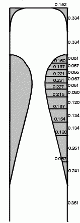
Tap 0 is an added position which brings the curve back to meet the outside diameter
of the 0.375 inch inlet tube, thus forming an expansion chamber behind the full-width
nozzle inlet given by the original demonstration nozzle tap positions 1 through 14.
Using a pattern generated from the nozzle tap position data a core of modeling
clay was formed to fill the nozzle void space during the casting process. The clay
was kneaded and rolled to the required 0.375 inch thickness and then cut to the proper
shape by running an X-Acto(tm) knife blade around the pattern. The 0.375 inch OD tube was
stuck into the expansion chamber end of the clay form to complete the void mold piece.
![[inlet nozzle]](./thumb/tt/nozzle_05-t.jpg)
![[inlet nozzle]](./thumb/tt/nozzle_02-t.jpg)
Conveniently, I had a section of square metal tubing which had the precise thickness
required for clamping the nozzle assembly's 0.091 inch thick polycarbonate side pieces
to so that they ended up spaced apart at the same outside width as the outside width
of the turbine housing. So, laying a piece of 0.091 inch thick polycarbonate sheet cut
to fit between the clamped side pieces on the metal tube as a bottom for the nozzle
assembly, centering the clay core piece on this botton sheet, and drilling a 0.375 inch
hole in another piece of 0.091 inch polycarbonate so that the hole's outside edge was
0.091 inches from the edge of the sheet, and fitting this hole over the 0.375 inch OD
polystyrene tube extending from the clay core piece to cap the inlet end of the nozzle
assembly was all that was required to make the nozzle core mold. Another piece of 0.091
inch polystyrene sheet was cut to make a top piece for the nozzle, but this piece was
not actually installed until after the casting process was completed.
![[inlet nozzle]](./thumb/tt/nozzle_08-t.jpg)
![[inlet nozzle]](./thumb/tt/nozzle_09-t.jpg)
Sealing up the gaps with masking tape and pouring catalyzed casting resin to slightly
overfill the the mold form produces the actual nozzle curve side pieces. Prior to pouring
the casting resin was degassed using the simple vacuum chamber as described in the
subsection titled "A simple vacuum chamber" that follows. Degassing helps prevent bubbles
from forming in the casting resin as it cures.
Since there are bound to be some leaks and spills no matter how carefully you try and seal
the mold pieces, a piece of waxed paper was wrapped around the square metal tube before the
mold pieces were clamped in place for final assembly. Without that, once the casting resin
has cured, it could end up being very difficult to remove the nozzle assembly from the metal
tube it was clamped to.
![[inlet nozzle]](./thumb/tt/nozzle_11-t.jpg)
![[inlet nozzle]](./thumb/tt/nozzle_14-t.jpg)
Once the casting resin was fully cured, the excess extensions of the 0.091 inch polycarbonate
sheet pieces were removed by various sorts of clamping, filing, scraping, and sawing
machinations; involving square metal stock pieces, small c-clamps, a machinest's vice, an
X-Acto saw, a cabinet scraper, and a Dremel tool with a cutoff wheel installed.
![[inlet nozzle]](./thumb/tt/nozzle_19-t.jpg)
![[inlet nozzle]](./thumb/tt/nozzle_20-t.jpg)
![[inlet nozzle]](./thumb/tt/nozzle_21-t.jpg)
![[inlet nozzle]](./thumb/tt/nozzle_22-t.jpg)
![[inlet nozzle]](./thumb/tt/nozzle_23-t.jpg)
With the side and bottom pieces trimmed and squared, and the excess casting resin filed
flush with the top of the side pieces, the clay core mold piece was removed by first
digging it out, and then scraping the edges of the newly cast nozzle side pieces with an
X-Acto blade knife. (Note at this point the nozzle's polycarbonate end piece was left
extended to allow easier alignment of the yet to be installed nozzle top piece.)
![[inlet nozzle]](./thumb/tt/nozzle_24-t.jpg)
![[inlet nozzle]](./thumb/tt/nozzle_25-t.jpg)
After cleaning out the clay mold core, the nozzle's 0.091 inch polycarbonate top piece was
installed by running a bead of gel style cyanoacrylate glue around the top edge of the cast
resin piece and clamping the precut polycarbonate sheet into place. After the cyanoacrylate
glue cured, the extension of the nozzle end piece was trimmed flush with the nozzle top piece.
![[inlet nozzle]](./thumb/tt/nozzle_26-t.jpg)
![[inlet nozzle]](./thumb/tt/nozzle_27-t.jpg)
The final result was a nozzle with outside width the same as the width of the turbine housing,
and an exit port size of 0.735 by 0.377 inches. The final exit port size is well close enough
to the design port size of 0.680 by 0.375 inches for our purposes.
![[inlet nozzle]](./thumb/tt/nozzle_28-t.jpg)
The nozzle was installed into the turbine housing by cutting a slot in both housing side pieces
with a hacksaw, using a piece of square metal stock clamped in place as a guide along marks
drawn to fit the nozzle. Once the slots were cut, the nozzle was set in place and marked for
shaping of the nozzle exit port region to have the same curve as the runner holes in the turbine
housing side pieces. The nozzle was then shaped to the marked curve using a small sanding drum
in a Dremel tool. Once the nozzle was shaped to fit the turbine housing side piece runner holes,
it was fixed in place by drilling three holes each in two pieces of 0.25 inch square metal stock
about 1 inch long, the two outer holes tapped for 4-40 machine screws, and the middle hole
drilled for loose fit of a 4-40 machine screw. These metal pieces were attached to the outside
of the turbine housing side pieces by 4-40 screws inserted through holes drilled above an below
the nozzle slot, and the nozzle itself was drilled and tapped to accept 4-40 machine screws
inserted through the middle holes in the 0.25 inch square stock pieces. All the screw holes were
countersunk for the tapered machine screw heads.
![[inlet nozzle]](./thumb/tt/nozzle_30-t.jpg)
![[inlet nozzle]](./thumb/tt/nozzle_31-t.jpg)
![[inlet nozzle]](./thumb/tt/nozzle_34-t.jpg)
![[inlet nozzle]](./thumb/tt/nozzle_35-t.jpg)
![[inlet nozzle]](./thumb/tt/nozzle_36-t.jpg)
A simple vacuum chamber:
Probably more a matter of just being anal, than being of any great necessity for this
project, but, degassing casting resin can be helpful in preventing bubbles from
forming in the resin as it cures, which makes for a prettier cast. And, in the case
of something like the nozzle being constructed here, degassing can help prevent voids
caused by bubbles that adhered to the clay mold core from appearing in the inner
sidewalls of the final item when the clay is removed. Degassing is performed by
exposing the catalyzed resin to vacuum for about half of its cure time, then pouring
the resin. Gas (air) in the resin is pulled into the vacuum so it is not available
later for bubble formation.
A simple vacuum chamber was constructed out of a large glass jar, originally containing
3-bean salad, and having an opening diameter of about 3-1/2 inches, plus the threaded
sleeve used to run wire through from the bulb socket to the base of a standard household
lamp. The threaded sleeve was inserted into a hole punched in the metal screwtop lid of
the glass jar, and a nut run up the sleeve to the jar lid from both the top and the bottom,
clamping the sleeve in place. The sleeve and nuts were then sealed to the jar lid with
a layer of red RTV silicon rubber. A piece of 0.25 inch ID vinyl tubing was slipped over
the end of the threaded sleeve extending from the top of the jar lid for attaching the
jar to a vacuum source. A clear plastic "party cup" with a wire bridle was used for a
resin holder.
![[vacuum chamber]](./thumb/tt/vacuum_01-t.jpg)
![[vacuum chamber]](./thumb/tt/vacuum_02-t.jpg)
The source of vacuum was a hand pump of the type used by automotive mechanics for testing
smog systems and break systems. In use, with a fair bit of continuous pumping effort, it
was possible to pull about 25 inches of vacuum on casting resin in the cup inside the jar.
![[vacuum chamber]](./thumb/tt/vacuum_03-t.jpg)
To use the chamber you must pump continuously for the degassing period (about 7 minutes
in the case of the 15 minute cure time casting resin used here). If you just pump to the
maximum possible vacuum level, then sit back and relax, the gas in the resin will expand
out to fill the vacuum, but no more will leave after that.
Bubbles will form in the resin during the degassing period, and a little flurry of bubbling
when the vacuum is removed is common. Once the vacuum is removed and the bubbling competed,
the resin should appear clear with perhaps a few bubbles still on its surface. Since you've
already used up half your cure time, pour quickly.
![[vacuum chamber]](./thumb/tt/vacuum_04-t.jpg)
![[vacuum chamber]](./thumb/tt/vacuum_05-t.jpg)
The housing:
The new turbine housing uses the same base plate and bearing mounts as the original housing.
But, the mounts have been reinforced by fitting a piece of 0.25 inch thick by 1 inch wide
aluminum bar stock between the bearing mount side pieces, attaching them to the bearing
mounts by drilling, tapping, and countersinking for 4-40 flat head machine screws. The
aluminum bar pieces are drilled and tapped to accept 10-14 screws for attaching the bearing
mounts to the turbine base plate, and also drilled and tapped to accept 4-40 screws passed
through 0.25 inch square steel stock pieces used to stiffen the turbine base plate.
Side pieces for the new 6 inch turbine runner housing were cut from 0.223 inch clear
polycarbonate sheet using a jigsaw with a fine tooth carpentry blade following a taped on
pattern. Holes 3.125 inch in radius to allow installation of the turbine runner were also
cut in the side pieces by following the taped on pattern with the jigsaw. Slots for the
inlet nozzle assembly were cut in the side pieces as described in the section above titled
"The inlet nozzle." Spacers for the side plates were cut from 0.25 inch thick 0.75 inch wide
aluminum bar stock. The side pieces were drilled and countersunk for 4-40 machine screws to
attach the aluminum bar spacers. The aluminum bar spacers were drilled and tapped to accept
4-40 machine screws to attach the side plates. The bottom spacer was also drilled and tapped
for 10-24 machine screws to attach the runner housing to the turbine base plate, and drilled
and tapped for 4-40 screws passed through 0.25 inch square steel stock pieces used to
stiffen the turbine base plate.
![[modified housing]](./thumb/tt/housing_13-t.jpg)
![[modified housing]](./thumb/tt/housing_05-t.jpg)
Circular vent plates were cut from 0.091 inch thick polycarbonate sheet by clamping the material
between 0.5 inch square metal bar stock pieces, scribing and snapping off pieces to form a near
round shape, then trimming them smooth using a pair of tin snips. Vent holes 1.25 inches in
radius were cut in the center of the vent plates using a holesaw chucked in a drill press.
![[modified housing]](./thumb/tt/housing_01-t.jpg)
![[modified housing]](./thumb/tt/housing_02-t.jpg)
The side plates were drilled and tapped for eight 4-40 machine screws around the circumference
of the turbine runner holes, and in a matching pattern, the vent plates were drilled and
countersunk for 4-40 machine screws, for attachment of the vent plates to the side panels.
![[modified housing]](./thumb/tt/housing_11-t.jpg)
The volute was sealed by attaching a strip of 0.030 inch thick clear plastic sheet between
the side pieces with 0.125 inch thick double sided foam tape applied to the circumference
of the turbine runner installation holes, and across the bottom of the mouth of the inlet
nozzle. The strip was fit first with the inward facing side of the double sided tape covered
so that it would not stick in place before its time. The strip was marked for cutting an
opening for the inlet nozzle exit port so that the bottom of the nozzle is flush with the
cut opening, but the top of the cut is at the top of the runner hole, not at the top of the
inlet nozzle exit port. This allows unobstructed flow out of the nozzle. A small strip of
the 0.030 inch clear sheet the cut to the width of the space between the turbine side pieces
was glued to the main strip so that it extends back from the top of the runner hole and
overlaps the top of the inlet nozzle and completes sealing of the volute. The main strip was
cut wide and trimmed off with an X-Acto knife after the inner double sided foam tape surface
was exposed and the main strip set in its final position against the tape.
![[volute shroud]](./thumb/tt/shroud_01-t.jpg)
![[volute shroud]](./thumb/tt/shroud_03-t.jpg)
![[volute shroud]](./thumb/tt/shroud_06-t.jpg)
![[volute shroud]](./thumb/tt/shroud_04-t.jpg)
![[volute shroud]](./thumb/tt/shroud_09-t.jpg)
The original bearing thrust screw adjustment was discarded in favor of set screw collars
slipped onto the turbine runner shaft inside of the bearings. With the bearings pressed
into their recepticals, the turbine runner is centered in the turbine housing, and the set
screw collars are then slid up against the bearings and their set screws tightened to
retain the bearings and fix the postion of the runner in the housing.
![[modified housing]](./thumb/tt/housing_04-t.jpg)
Putting it all together:
As can be seen in the following photo sequence, the turbine can now easily be completely
disassembled and reassembled, allowing changing runners for different test. Plus, there
is even a spot for a bit of duct tape. No home project is complete without it!
![[housing assembly]](./thumb/tt/assemble_01-t.jpg)
![[housing assembly]](./thumb/tt/assemble_02-t.jpg)
![[housing assembly]](./thumb/tt/assemble_03-t.jpg)
![[housing assembly]](./thumb/tt/assemble_04-t.jpg)
![[housing assembly]](./thumb/tt/assemble_05-t.jpg)
![[housing assembly]](./thumb/tt/assemble_06-t.jpg)
![[housing assembly]](./thumb/tt/assemble_07-t.jpg)
![[housing assembly]](./thumb/tt/assemble_10-t.jpg)
Dimensioned drawings:
Here are dimensioned drawings of the major pieces of the 6 inch turbine housing upgrade components,
plus runner disc and star washer drawings. Note the washer drawing shows both short spoke and long
spoke varieties. Short spoke star washers were used in constructing the transparent runner assembly
described below. [cite tesla long spoke improvement patent here someday]
Click on thumbnails for fixed size jpeg images. Click on the link below a thumbnail for an svg image.
You can download svg image viewers for most browsers from www.adobe.com.
![[Side Panel]](./thumb/tt/SidePanel-t.jpg)
![[Vent Plate]](./thumb/tt/VentPlate-t.jpg)
![[Separator Plates]](./thumb/tt/SeparatorPlates-t.jpg)
![[Bearing Mount Pad]](./thumb/tt/BearingMountPad-t.jpg)
SidePanel.svg
VentPlate.svg
SeparatorPlates.svg
BearingMountPad.svg
![[Runner Disc]](./thumb/tt/4SpokeRunner-t.jpg)
![[Star Washers]](./thumb/tt/4SpokeWasher-t.jpg)
![[Nozzle Core]](./thumb/tt/NozzleCore-t.jpg)
4SpokeRunner.svg
4SpokeWasher.svg
NozzleCore.svg
I can see clearly now...
(c.a., July 2003)
With a transparent runner it should be possible to see streamline flow patters
between runner discs by injecting a tracer into the driving gas stream. Even if
it proves difficult to characterize, if it works it should at least look cool.
So, of course, here is how I built first the jigs to build one, and then built one.
Arc cutter jig:
The arc cutter jig is used to cut circles for runner discs and star washers, and for
cutting the arcs necessary for the vent cutter jig. It has two parts, a cutting board
with a 0.375 inch diameter metal peg extending perpendicular to it's surface, and a
Dremel tool mounted in a router jig with that jig screwed to a 0.25 inch thick flat
aluminum plate. A 0.375 inch diameter center hole was drilled near one end of the
aluminum plate, and holes spaced down the plate appropriately for each desired radius
for the Dremel cutter to extend through. Four holes were drilled through the Dremel
router base for 3/16th inch machine screws that attach the router plate to the aluminum
plate. Spacing for the router bit from the center hole for each arc is set by the
placement of 4 base plate mounting screw holes in the aluminum base plate.
![[arc cutter jig]](./thumb/tt/arcjig_04-t.jpg)
![[arc cutter jig]](./thumb/tt/arcjig_01-t.jpg)
![[arc cutter jig]](./thumb/tt/arcjig_02-t.jpg)
![[arc cutter jig]](./thumb/tt/arcjig_03-t.jpg)
Drilling a 0.375 inch hole in the material to be cut, setting the material with its
hole over the metal peg on the cutting board, and placing then placing the 0.375 inch
center hole in the aluminum router plate over the metal peg allows the material to be
cut with a radius determined by the distance from the center of the metal peg in the
cutting board to the edge of the Dremel router bit closest to the metal peg. On thin
material it is reasonable to plunge start the cut. For thick material, it is better to
drill a starting hole for the Dremel router cutter to pass through.
Vent cutter jig:
The vent cutter jig consists of several parts, including a pattern piece that a
Dremel router with a cutter having a guide bearing is run inside of to cut the
vent holes, and several alignment and support pieces. To construct the vent cutter
jig, the arc cutter jig was used to cut two arcs relative to a 0.375 inch center
hole of the proper radii for the inner and outer edges of a runner disc vent hole.
To make the proper radius arcs, the excess width of the guide bearing over the
width of the router bit must be taken into account. Here, a 5/16th inch OD, 1/8th
inch ID high speed ball bearing intended for gas engine powered model race cars is
used for the guide bearding. The cutter is a 3/16th inch Dremel straight cutter
with 1/8th inch shaft. With the bearing slipped over the cutter shaft, the cutter
edge will be 1/16th inch inside of whatever edge the bearing rides one, so, the
outer arc must be 1/16th inch outside of the desired outer vent arc, and the inner
arc must be 1/16th inch inside of the desired inner vent arc; similarly, the
straight sides of the vent jig must be displaced 1/16th inch away from the center
of the vent. Also, very important this, the half-width of the cutter must also be
taken into account. Besides the 1/16th inch offset for the guide bearing, the
thickness of the cutter from its own center must be compensated for in setting the
jig arcs. That means, for a 3/16th inch cutter the placement of the router on the
arc cutter aluminum plate must place the centerline of the cutter 3/32nds of an
inch inside the desired arc radius for an outside cut, and 3/32nds of an inch
outside the desired arc radius for an inside cut. This cutter diameter compensation
was made for all arcs available, both inside and out, in placing the mounting screw
holes on the arc cutter jig aluminum plate. So, only the 1/16th inch compensation
for the guide bearing was necessary in sizing the vent cutter jig pattern guide hole.
![[vent cutter jig]](./thumb/tt/ventjig_01-t.jpg)
![[vent cutter jig]](./thumb/tt/ventjig_02-t.jpg)
![[vent cutter jig]](./thumb/tt/ventjig_03-t.jpg)
![[vent cutter jig]](./thumb/tt/ventjig_04-t.jpg)
With proper arcs and straight sides cut, a piece of waxed paper was taped to the
bottom of the the arc cutter guide plate under the guide hole region, and the
excess arc cut areas were blocked with cut pieces of cardboard. The excess arc
cut areas where then filled with 5 minute epoxy resin to provide a continuous
pattern surface for the guide bearing to ride on.
![[vent cutter jig]](./thumb/tt/ventjig_05-t.jpg)
![[vent cutter jig]](./thumb/tt/ventjig_06-t.jpg)
Holes for two alignment pins cut from 3/16th inch brass welding rod were added to the
arc cutter jig cutting board, one that aligns with one of the runner inner assembly
rod holes, and one that aligns with one of the runner outer assembly rod holes.
With these, it so possible by rotating and flipping a runner disc on the 0.375 guide
peg in the cutting board to make proper alignment for all four vent holes in a runner
relative to the guide pattern hole in the vent cutter jig.
![[vent cutter jig]](./thumb/tt/ventjig_07-t.jpg)
To complete the vent cutter jig a clamping plate assembly was construted. Along with
the hole for the 0.375 inch guide peg already present, two 3/16th inch holes for the
welding rod guide pins were added to the vent hole bearing guide pattern plate. On
the end of the bearing guide plate away from the 0.375 inch peg hole, holes were
drilled and counter sunk to allow attaching a strip of 0.223 inch material about an
inch wide to act as a spacer when cutting verts in 0.223 inch thich discs and as a
place for clamping the jig to the cutting board once all the parts and materials are
properly set on the guide peg and pins.
![[vent cutter jig]](./thumb/tt/ventjig_08-t.jpg)
![[vent cutter jig]](./thumb/tt/ventjig_09-t.jpg)
When cutting vents in 0.223 inch material, only the cutting board with alignment peg
and pins, and the bearing guide plate are required to make a cut. But, when cutting
thinner material you need to compensate for the difference in thicknesses. This is
accomplished with a strip of material the same thickness as the material you are cutting
placed under the 0.223 inch strip on the end of the bearing guide plate, and also another
0.223 inch plate with a hole centered under and larger than the bearing guide hole, plus
holes for the cutting board guide peg and pins. This piece is placed on top of the thin
material being cut to level the surface of the guide plate for the Dremel router.
![[vent cutter jig]](./thumb/tt/ventjig_10-t.jpg)
![[vent cutter jig]](./thumb/tt/ventjig_11-t.jpg)
The first test of the vert cutter jig was on an assembly hole pattern jig for 6 inch
turbine discs. As you can see, counter clockwise from the bottom, the quality of the
cut holes improves greatly. The bottom vent hole is particularly rough as on that pass
both the cut pocket in the cutting board and the vent hole were being produced. With
no good path to escape wood chips caused a lot of chatter and heating (which makes the
material turn "gummy"). The remainder are just improvement with practice.
![[hole pattern jig]](./thumb/tt/holepattern_05-t.jpg)
Hole pattern jig:
Consistency counts; particularly when building something with the balance requirements
of a turbine. So, to facilitate drilling holes in runner discs in something like the
same place for every copy, a hole pattern jig was made from a disc of 0.223 inch clear
polycarbonate material. The disc was cut roughly with a jigsaw to slightly oversized
for a 6 inch turbine, and a paper pattern then taped to the disc. The hole positions
were transferred from the pattern to the disc with a spring loaded metal punch, and
the holes drilled appropriately, 0.375 inch for the axel shaft and 0.125 inch for all
the assembly rod holes. The disc was then mounted in a lathe and turned to the correct
diameter. In use, a 0.375 inch hole is drilled in the material a disc is to be produced
from, and that material is set on the guide peg in the arc cutter cutting board. The
hole pattern jig is set over the disc material and a c-clamp used to hold the pattern
and disc material in place. Then a 0.125 inch transfer punch and a small hammer are
used to mark all the assembly rod holes relative to the 0.375 inch axel hole. With the
holes marked the disc is unclamped, the transfer marks made into true punch marks using
the spring loaded metal punch, and the punch marks are used as a guide to drill the
0.125 inch assembly rod hole with a drill press.
![[hole pattern jig]](./thumb/tt/holepattern_01-t.jpg)
![[hole pattern jig]](./thumb/tt/holepattern_02-t.jpg)
![[hole pattern jig]](./thumb/tt/holepattern_03-t.jpg)
![[hole pattern jig]](./thumb/tt/holepattern_04-t.jpg)
![[hole pattern jig]](./thumb/tt/holepattern_06-t.jpg)
Transparent runner discs:
Finally! With all the required tools, now we can make some runner discs. Two 0.223 inch
thick discs for the runner ends, and four 0.091 inch discs for the inner runner, with
five 0.031 inch thick star washers makes a complete runner assembly stack 0.865 inches
thick. This is plenty close enough to the original pump style runner's 0.960 inch thickness
to use in the new turbine housing with no modifications to the housing. So, these discs,
plus a couple of others, were cut using the new jigs.
![[clear discs]](./thumb/tt/cleardisc_01-t.jpg)
![[clear discs]](./thumb/tt/cleardisc_02-t.jpg)
![[clear discs]](./thumb/tt/cleardisc_04-t.jpg)
Transparent runner star washers:
(c.a., April 2004)
That's transparent-runner star washers, not transparent runner-star-washers. Back the better
part of a year ago I drilled and cut discs from 0.031 inch white polystyrene sheet to use
making star washers for the transparent turbine runner. (It really only matters that the
runner discs are transparent to see dye flow. Nothing goes between the star washers.) Just a
matter of using the vent cutter jig and trimming off the excess with an X-Acto blade knife
to finish them.
![[starwashers]](./thumb/tt/transwasher_04-t.jpg)
![[starwashers]](./thumb/tt/transwasher_03-t.jpg)
![[starwashers]](./thumb/tt/transwasher_01-t.jpg)
![[starwashers]](./thumb/tt/transwasher_05-t.jpg)
![[starwashers]](./thumb/tt/transwasher_06-t.jpg)
Transparent runner assembly:
With everything fitting together nicely, time to relocate to a more dust free envrionment, wash
all the greasy finger prints off the runner discs and star washers, and let them dry.
![[transparent runner assembly]](./thumb/tt/transrunner_01-t.jpg)
![[transparent runner assembly]](./thumb/tt/transrunner_02-t.jpg)
With everything clean, and a board with a 0.375 inch hole drilled squarely through it as well
as holes partially through for all the assembly rods, using the hole drilling jig as a guide,
we're ready to start sticking things together. Literally, with polystyrene plastic cement.
First thing, and if you already don't know this trick, you'll thank me for it later, do NOT
try and put the runner together with assembly rods of the same length! Rather, cut them so
that they can be placed in the assembly board in a spiral from tall rod to short rod with an
eighth to a quarter inch difference in length between each rod in the spiral sequence. This
way you can insert the first assembly rod into its hole, and slide it down a bit before you
have to insert the next rod into its hole, which means the first rod will not jump out of its
hole when you try and insert the second, etc., etc. Really. Do it this way. You'll save yourself
a trip to a pretty white room in a nice jacket with very long sleeves. (This trick also works
well for things like hand inserting can style op-amps into printed circut boards, by the way.
Just cut the leads in a similar spiral pattern.)
![[transparent runner assembly]](./thumb/tt/transrunner_04-t.jpg)
![[transparent runner assembly]](./thumb/tt/transrunner_05-t.jpg)
![[transparent runner assembly]](./thumb/tt/transrunner_06-t.jpg)
Once the first outer disc is in place flat on the assembly board, take the glue
brush and daub a bit around each assembly rod, and around the axle rod. Do this
for each disc once it is in place to lock the assembly rods at the proper
distance for disc separation. The stacking sequence is outer disc, star washer,
inner dsic, star washer, inner disc, star washer, inner disc, start washer,
inner disc, star washer, outer disc. Before placing a star washer first coat the
spokes of the runner disc it is to mate with with cement, and also its spokes on
the side it is to mate with. Then place the star washer and press it down firmly.
Similarly when you place a runner disc, coat the spokes of the star washer already
in place it is to mate with, and its own spokes on the mating side, then work it
down the assembly rods and press it frimly in place. To maintain the proper runner
disc spacing, place a small piece of 0.031 inch thick polystyrene near each
assembly rod and then press the runner disc spokes firmly down and more gently
press down near the 0.031 inch polystyrene pieces. Again, daub a little cement
around the assembly rods and the axle with each level assembled. The inner runner
discs are fairly stiff, so it isn't necessary to keep stacking 0.031 inch
polystyrene pieces all the way up the assembly at each assembly rod location. They
just need to be in place to set the distance between layers as they are assembled.
Of course, it isn't a bad idea to place a 0.031 inch piece into each level at the
time you press the runner disc into its final position before applying a daub of
glue around the closest assembly rod, just in case the glue is still soft in layers
below, but you can do that on a rod by rod basis so long as the runner is held
separate from the one below by 0.031 pieces all the way around.
![[transparent runner assembly]](./thumb/tt/transrunner_07-t.jpg)
![[transparent runner assembly]](./thumb/tt/transrunner_08-t.jpg)
![[transparent runner assembly]](./thumb/tt/transrunner_09-t.jpg)
![[transparent runner assembly]](./thumb/tt/transrunner_11-t.jpg)
![[transparent runner assembly]](./thumb/tt/transrunner_12-t.jpg)
Speaking of all the way around, note the alignmarks on each runner disc in the
assembled runner stack in the photo below. If you look closely, you'll see a
matching set on the assembly board. I said consistency counts. The hole drilling
jig is very consistent, but, it is not perfectly symmetric. Unless your's is
perfect, there will be a few tiny wobbles in the hole spacing, so you'll need to
mark your runner discs for proper alignment at assembly.
![[transparent runner assembly]](./thumb/tt/transrunner_14-t.jpg)
Once the stack is assembled, place 0.031 inch thick pieces of polystyrene in each
gap in alignment with two opposite spokes, then gently clamp those two spokes at
the hub and leave it overnight for the glue to cure. After that the completed runner
can be removed from the assembly board and the assembly rods trimmed off with an
X-Acto knife. (Be careful to not scratch up your nice transparent surfaces!)
![[transparent runner assembly]](./thumb/tt/transrunner_15-t.jpg)
![[transparent runner assembly]](./thumb/tt/transrunner_17-t.jpg)
![[transparent runner assembly]](./thumb/tt/transrunner_20-t.jpg)
As with the pump style turbine runner, a length of 0.25 inch diameter cold rolled
steel rod was driven through the 0.375 inch OD polystyrene axle tube to provide
extra rigidity. After that the runner was chucked in a lathe for a bit of truing.
You'll want to make shallow, slow passes with a very sharp and fine point cutter.
Otherwise you run the risk of sealing your gaps with rolled over material. A water
cooling mist might be appropriate, but not absolutely necessary. Even being careful
and slow, the gap edges are likely to flare slightly. This can be fixed by turning
the lathe chuck by hand while scraping the gap edges with an X-Acto knife blade.
For a finish, you can take a piece of fine wet-dry sanding paper and insert it
between and hold it on the gap edges while the chuck is spun at a few hundred rpm.
![[transparent runner assembly]](./thumb/tt/transrunner_21-t.jpg)
![[transparent runner assembly]](./thumb/tt/transrunner_22-t.jpg)
![[transparent runner assembly]](./thumb/tt/transrunner_23-t.jpg)
![[transparent runner assembly]](./thumb/tt/transrunner_25-t.jpg)
![[transparent runner assembly]](./thumb/tt/transrunner_26-t.jpg)
Transparent runner installation:
Simple. Remove the old pump style opaque runner and replace it with the new
transparent runner. A while back I decided it would be simpler to place a turbine
in something like an aquarium and inject vegetable dye into a water stream, rather
than try and figure out how to generate fine particle smoke on demand and inject
that into an air stream (and probably a lot easier on the environment); and, hence,
the link to the solar powered fluid mechanics lab at the top of this page. To that
end I drilled a small hole at an angle towards the outlet of the inlet nozzle and
inserted it a hypodermic needle for dye injection. This can be seen in some of the
photos below. A 0.031 inch thick white polystrene piece was cut to fit under one
of the circluar vent pieces on the turbine houseing to act as a background for
viewing injected dye.
![[removing opaque runner assembly]](./thumb/tt/turbdisassy_01-t.jpg)
![[installing transparent runner]](./thumb/tt/transassy_01-t.jpg)
![[installing transparent runner]](./thumb/tt/transassy_02-t.jpg)
![[dye
view contrast disc]](./thumb/tt/turbviewdisc_02-t.jpg)
![[turbine stay rod]](./thumb/tt/turbstayrod_01-t.jpg)
Take it for a spin!
(c.a., August 2004)
With the transparent runner turbine finished a few months ago, I haven't quit on this project,
but, I've been working mainly on adjunct portions, in particular, the Solar Powered Fluid
Mechanics Lab (SPFML). That has its own web page, which can be accessed from its link at the
top of this page.
Turbine testing via the SPFML will be documented on this page, but detailing the SPFML itself
will be left to the SPFML web page. Testing to date consists mainly of fixing leaks. However, I
did make a few attempts at dye injection for flow visualization. And, I've decided that it is
difficult to get it right, and very very messy. I'm giving up on dye injection and will be giving
hydrogen bubble flow visualization a try in the near future.
Below is a link to video of the transparent runner turbine spinning away via water flow in the SPFML.
![[first flow test]](./shared/jpg/first_turns_anim-t.jpg)
Visualization Upgrades
A few simple changes to the turbine were necessary to implement hydrogen bubbling visualization, and
expedite switching runners for investigating the effects of changing vent shapes and vent-to-runner
size ratios.
Bubbler electrodes:
Hydrogen bubble flow visualization works through a controlled electrical dissociation of water into
oxygen bubbles outside of the visualization region, and a very fine, pulsating stream of hydrogen
bubbles injected into the region of the flow to be visualized. The path followed by the hydrogen
bubble stream shows the flow streamlines.
The circuit used here for applying power to the water dissociation anode and cathode electrodes is
described on the Solar Powered Fluid Mechanics Laboratory page. Construction of the anode and cathode
electrodes and their attachment to the turbine housing is described below. During water dissociation,
oxygen is produced at the anode, and hydrogen is produced at the cathode.
anode:
(c.a., February 2005)
A circular piece about three inches in diameter punched from a thin sheet of copper was used for
the anode. The center of the disc was marked through a pattern drawn on a piece of tracing paper,
and an entry hole drilled then cut and filed large enough for the runner shaft bearing retaining
collars to slip through. The disc was then mounted on one of the turbine bearing stands using brass
tubing standoffs, 4-40 brass screws, and nylon insert lock nuts. The electrical connection to the
disc is made via a wire eyelet trapped under a wing nut on one of the mounting screws.
![[bubbler anode]](./thumb/tt/anode01-t.jpg)
![[bubbler anode]](./thumb/tt/anode03-t.jpg)
![[bubbler anode]](./thumb/tt/anode04-t.jpg)
![[bubbler anode]](./thumb/tt/anode05-t.jpg)
![[bubbler anode]](./thumb/tt/anode07-t.jpg)
![[bubbler anode]](./thumb/tt/anode11-t.jpg)
![[bubbler anode]](./thumb/tt/anode08-t.jpg)
![[bubbler anode]](./thumb/tt/anode09-t.jpg)
![[bubbler anode]](./thumb/tt/anode12-t.jpg)
cathode:
(c.a., October 2005)
The cathode was made from a 0.003 inch diameter piece of platinum wire threaded through two holes
drilled near the mouth of the nozzle so that the wire runs parallel to the runner shaft in the
center of the nozzle output stream.
![[bubbler cathode]](./thumb/tt/001&003Pt-t.jpg)
![[bubbler cathode]](./thumb/tt/003PtLabel-t.jpg)
Quick removal runner:
(c.a., October 2005)
The major modifications to the turbine housing of two-and-a-half years ago, (hard to believe
it has been that long!), did make it relatively easy to change runners. But, it still required
removing a lot of screws and a good idea of how all the bracing pieces are mounted to know which
screws to remove. That's OK when you're just fiddling about, but, particularly for demonstration
purposes, a bit slow and inconvenient. So, I made some changes that allow swapping runners without
need of a screwdriver.
Two 1-inch square blocks were cut from 1-by-3/4 inch aluminum bar. These were drilled and tapped so
they could be attached on top of the existing aluminum strip used to mount the bearing support on
the opposite side of the turbine housing from the hydrogen bubbler anode. The outer threaded holes
in the existing aluminum strip were aligned in the drill press using a transfer punch in the drill
chuck, then drilled out to allow 10-24 screws to pass through the strip and screw into the threaded
holes in the newly cut 1-inch square aluminum blocks.
![[quick removal mount]](./thumb/tt/quickmount_01-t.jpg)
![[quick removal mount]](./thumb/tt/quickmount_02-t.jpg)
![[quick removal mount]](./thumb/tt/quickmount_03-t.jpg)
![[quick removal mount]](./thumb/tt/quickmount_04-t.jpg)
![[quick removal mount]](./thumb/tt/quickmount_05-t.jpg)
![[quick removal mount]](./thumb/tt/quickmount_08-t.jpg)
![[quick removal mount]](./thumb/tt/quickmount_06-t.jpg)
![[quick removal mount]](./thumb/tt/quickmount_07-t.jpg)
![[quick removal mount]](./thumb/tt/quickmount_09-t.jpg)
The 1-inch square blocks provide sufficient backing for the bearing mount lexan pieces so that two 6-32
thread thumbscrews on each end of the assembly can be used to retain the bearing mount; allowing the
2-56 screws previously used to attach the bearing mount to the original aluminum strip to be
permanantly removed.
![[quick removal mount]](./thumb/tt/quickmount_10-t.jpg)
![[quick removal mount]](./thumb/tt/quickmount_11-t.jpg)
![[quick removal mount]](./thumb/tt/quickmount_12-t.jpg)
![[quick removal mount]](./thumb/tt/quickmount_13-t.jpg)
![[quick removal mount]](./thumb/tt/quickmount_14-t.jpg)
![[quick removal mount]](./thumb/tt/quickmount_15-t.jpg)
![[quick removal mount]](./thumb/tt/quickmount_16-t.jpg)
![[quick removal mount]](./thumb/tt/quickmount_17-t.jpg)
Now, by removing the 4 thumbscrews and pushing the bearing out of its pocket in the bearing mount
while tipping the mount away from the turbine housing, the bearing mount is easily removed for
access to the runner.
![[quick removal mount]](./thumb/tt/quickmount_18-t.jpg)
![[quick removal mount]](./thumb/tt/quickmount_19-t.jpg)
With the bearing mount out of the way, the housing vent plate still blocks the turbine runner
from being removed. To eliminate the need to use a screwdriver to remove the vent plate, I
disassembled the side of the turbine housing away from the hydrogen bubbler anode, and rethreaded
the 4-40 holes in the housing side panel to size 6-32. I then inserted 1/2 inch long 6-32 screws
from the inside out of the side panel so they could be used as studs for mounting the vent plate
with 6-32 wingnuts.
![[quick removal vent]](./thumb/tt/quickvent_01-t.jpg)
![[quick removal vent]](./thumb/tt/quickvent_02-t.jpg)
![[quick removal vent]](./thumb/tt/quickvent_03-t.jpg)
The lower screw required a little special attention. Since it backs up against the lower turbine
housing spacer, its hole had to be counter sunk, and a 6-32 flat head screw used in place of the
pan head screws used in the other holes.
![[quick removal vent]](./thumb/tt/quickvent_04-t.jpg)
![[quick removal vent]](./thumb/tt/quickvent_05-t.jpg)
With the turbine side panel remounted, and the holes in the vent plate resized for a loose fit on
6-32 screws, the vent plate is easily installed on or removed from the side panel via 6-32 wingnuts
on the side panel 6-32 studs. (The lower screw is only used for alignment. Without trimming the
wings, a wingnut won't quite turn there, and I didn't feel like customizing just one nut.)
![[quick removal vent]](./thumb/tt/quickvent_06-t.jpg)
![[quick removal vent]](./thumb/tt/quickvent_08-t.jpg)
![[quick removal vent]](./thumb/tt/quickvent_09-t.jpg)
Although not absolutely necessary, I chamfered the 1-inch square backing blocks to allow pulling
the runner straight out of the turbing housing without having to tilt the shaft in the opposite
bearing to get the runner past the backing blocks.
![[quick removal mount]](./thumb/tt/quickmount_21-t.jpg)
![[quick removal mount]](./thumb/tt/quickmount_22-t.jpg)
Now, with the thumbscrew and wingnut arrangement, runners can be swapped in a matter of a minute of so.
![[quick removal vent]](./thumb/tt/quickvent_07-t.jpg)
Portable Air Power:
(c.a., October 2005)
While all aspects of turbine testing could be performed in the Solar Powered Fluid Mechanics Lab,
some things might be done much more simply by just dumping air from a fixed volume tank at a known
starting pressure into a turbine and watching what happens. For example, comparing runner design
efficiencies can be done this way. With proper consideration of mass differences, whichever runner
spins the longest for the same application of air through the turbine is the most efficient.
For a small pressure vessel I used something that may be near impossible to come up with these days,
a designated 30-pound freon canister originally used in automotive repair shops for recharging air
conditioner systems some decades ago, back when chlorofluorocarbons weren't known to be quite so
dangerous to the ozone and such.
![[portable air]](./thumb/tt/airpower_01-t.jpg)
My father used to own a repair shop, and, a long long time ago,
I squirreled a couple of canisters away once they were emptied. (You never know when something
might be useful!) If you aren't as big a packrat as me, and you choose to do something like I did
here, you should be able to come up with some kind of small tank at a surplus yard, a hardware store,
or even an autoparts store.
Basically, I just hung a quick action ball valve, a tire inflator valve, and a pressure guage off
the output fitting of the tank. The tank has a 1/4-inch male flare tube outlet. For that connection
I used a 1/4-inch flare swivel into a flare to 1/4-inch male NPT (pipe thread) adapter. The NPT
adapter screws into an aluminum manifold which has a 1/4-inch NPT threaded hole on each end, and
three 1/8-inch NPT threaded holes across its top. On top of the manifold I installed the pressure
guage, the inflator valve and an 1/8-inch NPT plug to close the third hole. The guage with 1/8-inch
NPT connection I had laying around in a junk box for years. The aluminum manifold and inflator
valve with 1/8-inch NPT connection I ordered on-line from McMaster-Carr for about $12.00. The rest
of the parts I picked up at a local hardware store for about $10.00 more. The hardware store ball
valve has 1/4-inch NPT male thread on one end and 1/4-inch NPT female thread on the other. The
male thread was screwed into the end of the manifold opposite the tank connection, and a 3/8-inch
hose barb adapter with 1/4-inch male NPT was screwed into the female threads on the ball valve.
Except for the flare tube swivel, teflon thread tape was used to seal all connections.
![[portable air]](./thumb/tt/airpower_02-t.jpg)
![[portable air]](./thumb/tt/airpower_03-t.jpg)
![[portable air]](./thumb/tt/airpower_04-t.jpg)
As it sits in the last picture of the three immediately above, the tank and valve assembly works
fine. Close the ball valve, open the tank valve, pump up the tank via the inflator valve, connect
a hose from the barb connection to the turbine nozzle inlet tube, quickly open the ball valve, and
watch the turbine spin. No problem. However, as you may have noticed by now, I'm kind of anal. So,
I decided to hack up a few pieces of aluminum to make a platform to support the manifold and not
take the chance of at some point getting overly excited and cracking the tank's flare fitting
by slamming the ball valve open too hard. The manifold has predrilled holes suitable for 8-32
mounting screws.
![[portable air]](./thumb/tt/airpower_05-t.jpg)
![[portable air]](./thumb/tt/airpower_06-t.jpg)
![[portable air]](./thumb/tt/airpower_07-t.jpg)
![[portable air]](./thumb/tt/airpower_08-t.jpg)
![[portable air]](./thumb/tt/airpower_09-t.jpg)
While the tank and valve assembly does stand up on its own, it would still be easy to pull or kick
over. To reduce those possibilities, I slotted a few boards and made a cradle to keep things a bit
more stable.
![[portable air]](./thumb/tt/airpower_10-t.jpg)
![[portable air]](./thumb/tt/airpower_11-t.jpg)
![[portable air]](./thumb/tt/airpower_12-t.jpg)
Pumping it up with a high-volume bicycle pump isn't the worst workout I've ever had. But, I plan
to use a 12-volt automobile tire inflation compressor for repeated use. Those things can get a little
warm. So, as temperature of the air in the tank is a factor in the supplied volume, a thermal sensor
on the tank may be in order.
References:
(Clicking reference numbers here takes you to the text location of the reference.)
[1] Tahil, William, 1999. Theoretical Analysis of a Disk Turbine (2).
Tesla Engine Builders Association News (16):15-16.
Last updated 03Sept2006
Alan Swithenbank, alans@cuervo.stanford.edu
![[finished model]](./big/tt/assemble_08.jpg)
![[Pop. Sci. pg. 1]](./big/tt/ps55_tb_1.jpg)
![[Pop. Sci. pg. 2]](./big/tt/ps55_tb_2.jpg)
![[Pop. Sci. pg. 3]](./big/tt/ps55_tb_3.jpg)
![[first test rotor]](./big/tt/greyrotorshaft.jpg)
![[first test rotor]](./big/tt/greyrotorspacing.jpg)
![[first test shrouded turbine]](./big/tt/whiterotorside.jpg)
![[first test shrouded turbine]](./big/tt/whiterotoredge.jpg)
![[reworked shrouded turbine]](./big/tt/bearingmounttics.jpg)
![[reworked shrouded turbine]](./big/tt/bearingmounthubangle.jpg)
![[reworked shrouded turbine]](./big/tt/bearingmounthub.jpg)
![[reworked shrouded turbine]](./big/tt/flywheelside.jpg)
![[reworked shrouded turbine]](./big/tt/flywheelstraight.jpg)
![[reworked shrouded turbine]](./big/tt/flywheelangle.jpg)
![[reworked shrouded turbine]](./big/tt/flywheelclose.jpg)
![[6 in. diam, .031 in. gap]](./big/tt/turb-6_031.jpg)
![[6 in. diam, .02 in. gap]](./big/tt/turb-6_020.jpg)
![[8 in. diam, .031 in. gap]](./big/tt/turb-8_031.jpg)
![[8 in. diam, .02 in. gap]](./big/tt/turb-8_020.jpg)
![[12 in. diam, .031 in. gap]](./big/tt/turb-12_031.jpg)
![[12 in. diam, .020 in. gap]](./big/tt/turb-12_020.jpg)
![[turbtorque.xls]](./big/tt/SpreadCapture-1.jpg)
![[housing assembly]](./big/tt/assemble_09.jpg)
![[housing assembly]](./big/tt/runnerout_01.jpg)
![[inlet nozzle]](./big/tt/nozzle_05.jpg)
![[inlet nozzle]](./big/tt/nozzle_02.jpg)
![[inlet nozzle]](./big/tt/nozzle_08.jpg)
![[inlet nozzle]](./big/tt/nozzle_09.jpg)
![[inlet nozzle]](./big/tt/nozzle_11.jpg)
![[inlet nozzle]](./big/tt/nozzle_14.jpg)
![[inlet nozzle]](./big/tt/nozzle_19.jpg)
![[inlet nozzle]](./big/tt/nozzle_20.jpg)
![[inlet nozzle]](./big/tt/nozzle_21.jpg)
![[inlet nozzle]](./big/tt/nozzle_22.jpg)
![[inlet nozzle]](./big/tt/nozzle_23.jpg)
![[inlet nozzle]](./big/tt/nozzle_24.jpg)
![[inlet nozzle]](./big/tt/nozzle_25.jpg)
![[inlet nozzle]](./big/tt/nozzle_26.jpg)
![[inlet nozzle]](./big/tt/nozzle_27.jpg)
![[inlet nozzle]](./big/tt/nozzle_28.jpg)
![[inlet nozzle]](./big/tt/nozzle_30.jpg)
![[inlet nozzle]](./big/tt/nozzle_31.jpg)
![[inlet nozzle]](./big/tt/nozzle_34.jpg)
![[inlet nozzle]](./big/tt/nozzle_35.jpg)
![[inlet nozzle]](./big/tt/nozzle_36.jpg)
![[vacuum chamber]](./big/tt/vacuum_01.jpg)
![[vacuum chamber]](./big/tt/vacuum_02.jpg)
![[vacuum chamber]](./big/tt/vacuum_03.jpg)
![[vacuum chamber]](./big/tt/vacuum_04.jpg)
![[vacuum chamber]](./big/tt/vacuum_05.jpg)
![[modified housing]](./big/tt/housing_13.jpg)
![[modified housing]](./big/tt/housing_05.jpg)
![[modified housing]](./big/tt/housing_01.jpg)
![[modified housing]](./big/tt/housing_02.jpg)
![[modified housing]](./big/tt/housing_11.jpg)
![[volute shroud]](./big/tt/shroud_01.jpg)
![[volute shroud]](./big/tt/shroud_03.jpg)
![[volute shroud]](./big/tt/shroud_06.jpg)
![[volute shroud]](./big/tt/shroud_04.jpg)
![[volute shroud]](./big/tt/shroud_09.jpg)
![[modified housing]](./big/tt/housing_04.jpg)
![[housing assembly]](./big/tt/assemble_01.jpg)
![[housing assembly]](./big/tt/assemble_02.jpg)
![[housing assembly]](./big/tt/assemble_03.jpg)
![[housing assembly]](./big/tt/assemble_04.jpg)
![[housing assembly]](./big/tt/assemble_05.jpg)
![[housing assembly]](./big/tt/assemble_06.jpg)
![[housing assembly]](./big/tt/assemble_07.jpg)
![[housing assembly]](./big/tt/assemble_10.jpg)
![[Side Panel]](./big/tt/SidePanel.jpg)
![[Vent Plate]](./big/tt/VentPlate.jpg)
![[Separator Plates]](./big/tt/SeparatorPlates.jpg)
![[Bearing Mount Pad]](./big/tt/BearingMountPad.jpg)
![[Runner Disc]](./big/tt/4SpokeRunner.jpg)
![[Star Washers]](./big/tt/4SpokeWasher.jpg)
![[Nozzle Core]](./big/tt/NozzleCore.jpg)
![[arc cutter jig]](./big/tt/arcjig_04.jpg)
![[arc cutter jig]](./big/tt/arcjig_01.jpg)
![[arc cutter jig]](./big/tt/arcjig_02.jpg)
![[arc cutter jig]](./big/tt/arcjig_03.jpg)
![[vent cutter jig]](./big/tt/ventjig_01.jpg)
![[vent cutter jig]](./big/tt/ventjig_02.jpg)
![[vent cutter jig]](./big/tt/ventjig_03.jpg)
![[vent cutter jig]](./big/tt/ventjig_04.jpg)
![[vent cutter jig]](./big/tt/ventjig_05.jpg)
![[vent cutter jig]](./big/tt/ventjig_06.jpg)
![[vent cutter jig]](./big/tt/ventjig_07.jpg)
![[vent cutter jig]](./big/tt/ventjig_08.jpg)
![[vent cutter jig]](./big/tt/ventjig_09.jpg)
![[vent cutter jig]](./big/tt/ventjig_10.jpg)
![[vent cutter jig]](./big/tt/ventjig_11.jpg)
![[hole pattern jig]](./big/tt/holepattern_05.jpg)
![[hole pattern jig]](./big/tt/holepattern_01.jpg)
![[hole pattern jig]](./big/tt/holepattern_02.jpg)
![[hole pattern jig]](./big/tt/holepattern_03.jpg)
![[hole pattern jig]](./big/tt/holepattern_04.jpg)
![[hole pattern jig]](./big/tt/holepattern_06.jpg)
![[clear discs]](./big/tt/cleardisc_01.jpg)
![[clear discs]](./big/tt/cleardisc_02.jpg)
![[clear discs]](./big/tt/cleardisc_04.jpg)
![[starwashers]](./big/tt/transwasher_04.jpg)
![[starwashers]](./big/tt/transwasher_03.jpg)
![[starwashers]](./big/tt/transwasher_01.jpg)
![[starwashers]](./big/tt/transwasher_05.jpg)
![[starwashers]](./big/tt/transwasher_06.jpg)
![[transparent runner assembly]](./big/tt/transrunner_01.jpg)
![[transparent runner assembly]](./big/tt/transrunner_02.jpg)
![[transparent runner assembly]](./big/tt/transrunner_04.jpg)
![[transparent runner assembly]](./big/tt/transrunner_05.jpg)
![[transparent runner assembly]](./big/tt/transrunner_06.jpg)
![[transparent runner assembly]](./big/tt/transrunner_07.jpg)
![[transparent runner assembly]](./big/tt/transrunner_08.jpg)
![[transparent runner assembly]](./big/tt/transrunner_09.jpg)
![[transparent runner assembly]](./big/tt/transrunner_11.jpg)
![[transparent runner assembly]](./big/tt/transrunner_12.jpg)
![[transparent runner assembly]](./big/tt/transrunner_14.jpg)
![[transparent runner assembly]](./big/tt/transrunner_15.jpg)
![[transparent runner assembly]](./big/tt/transrunner_17.jpg)
![[transparent runner assembly]](./big/tt/transrunner_20.jpg)
![[transparent runner assembly]](./big/tt/transrunner_21.jpg)
![[transparent runner assembly]](./big/tt/transrunner_22.jpg)
![[transparent runner assembly]](./big/tt/transrunner_23.jpg)
![[transparent runner assembly]](./big/tt/transrunner_25.jpg)
![[transparent runner assembly]](./big/tt/transrunner_26.jpg)
![[removing opaque runner assembly]](./big/tt/turbdisassy_01.jpg)
![[installing transparent runner]](./big/tt/transassy_01.jpg)
![[installing transparent runner]](./big/tt/transassy_02.jpg)
![[dye
view contrast disc]](./big/tt/turbviewdisc_02.jpg)
![[turbine stay rod]](./big/tt/turbstayrod_01.jpg)
![[first flow test]](./shared/gifs/first_turns_anim.gif)
![[bubbler anode]](./big/tt/anode01.jpg)
![[bubbler anode]](./big/tt/anode03.jpg)
![[bubbler anode]](./big/tt/anode04.jpg)
![[bubbler anode]](./big/tt/anode05.jpg)
![[bubbler anode]](./big/tt/anode07.jpg)
![[bubbler anode]](./big/tt/anode11.jpg)
![[bubbler anode]](./big/tt/anode08.jpg)
![[bubbler anode]](./big/tt/anode09.jpg)
![[bubbler anode]](./big/tt/anode12.jpg)
![[bubbler cathode]](./big/tt/001&003Pt.jpg)
![[bubbler cathode]](./big/tt/003PtLabel.jpg)
![[quick removal mount]](./big/tt/quickmount_01.jpg)
![[quick removal mount]](./big/tt/quickmount_02.jpg)
![[quick removal mount]](./big/tt/quickmount_03.jpg)
![[quick removal mount]](./big/tt/quickmount_04.jpg)
![[quick removal mount]](./big/tt/quickmount_05.jpg)
![[quick removal mount]](./big/tt/quickmount_08.jpg)
![[quick removal mount]](./big/tt/quickmount_06.jpg)
![[quick removal mount]](./big/tt/quickmount_07.jpg)
![[quick removal mount]](./big/tt/quickmount_09.jpg)
![[quick removal mount]](./big/tt/quickmount_10.jpg)
![[quick removal mount]](./big/tt/quickmount_11.jpg)
![[quick removal mount]](./big/tt/quickmount_12.jpg)
![[quick removal mount]](./big/tt/quickmount_13.jpg)
![[quick removal mount]](./big/tt/quickmount_14.jpg)
![[quick removal mount]](./big/tt/quickmount_15.jpg)
![[quick removal mount]](./big/tt/quickmount_16.jpg)
![[quick removal mount]](./big/tt/quickmount_17.jpg)
![[quick removal mount]](./big/tt/quickmount_18.jpg)
![[quick removal mount]](./big/tt/quickmount_19.jpg)
![[quick removal vent]](./big/tt/quickvent_01.jpg)
![[quick removal vent]](./big/tt/quickvent_02.jpg)
![[quick removal vent]](./big/tt/quickvent_03.jpg)
![[quick removal vent]](./big/tt/quickvent_04.jpg)
![[quick removal vent]](./big/tt/quickvent_05.jpg)
![[quick removal vent]](./big/tt/quickvent_06.jpg)
![[quick removal vent]](./big/tt/quickvent_08.jpg)
![[quick removal vent]](./big/tt/quickvent_09.jpg)
![[quick removal mount]](./big/tt/quickmount_21.jpg)
![[quick removal mount]](./big/tt/quickmount_22.jpg)
![[quick removal vent]](./big/tt/quickvent_07.jpg)
![[portable air]](./big/tt/airpower_01.jpg)
![[portable air]](./big/tt/airpower_02.jpg)
![[portable air]](./big/tt/airpower_03.jpg)
![[portable air]](./big/tt/airpower_04.jpg)
![[portable air]](./big/tt/airpower_05.jpg)
![[portable air]](./big/tt/airpower_06.jpg)
![[portable air]](./big/tt/airpower_07.jpg)
![[portable air]](./big/tt/airpower_08.jpg)
![[portable air]](./big/tt/airpower_09.jpg)
![[portable air]](./big/tt/airpower_10.jpg)
![[portable air]](./big/tt/airpower_11.jpg)
![[portable air]](./big/tt/airpower_12.jpg)